This was a project that I worked for UBC Formula Electric
, from September of 2020 up until December of 2020. The tractive system active light (TSAL) is sort of like
a beacon on top of the car which indicates when the tractive system is active (when the car is turned on).
It uses constant current drivers to ensure that equal amounts of current go through each LED, and they use
as little power as possible to maximize efficiency.
The requirements for the project were:
Design must be made using your own git branch and updating the existing TSAL project
Must follow the PCB specification document located in the Electrical Systems folder on google drive
Inputs to the board are +24V, RED_EN (5V), GREEN_EN(5V), GND
According to the rules, when RED_EN is on, the TSAL must flash at 2 to 5 hz. This can be achieved with a 555 timer chip, which will also need to be implemented.
Board to wire connections must be plated through-holes large enough to accommodate 22AWG wire
There must be 12 LEDs total on the board, 6 on the front, and 6 on the back. For each group of 6, 3 must be green and 3 must be red. The LED part numbers have to be the same as the previous design.
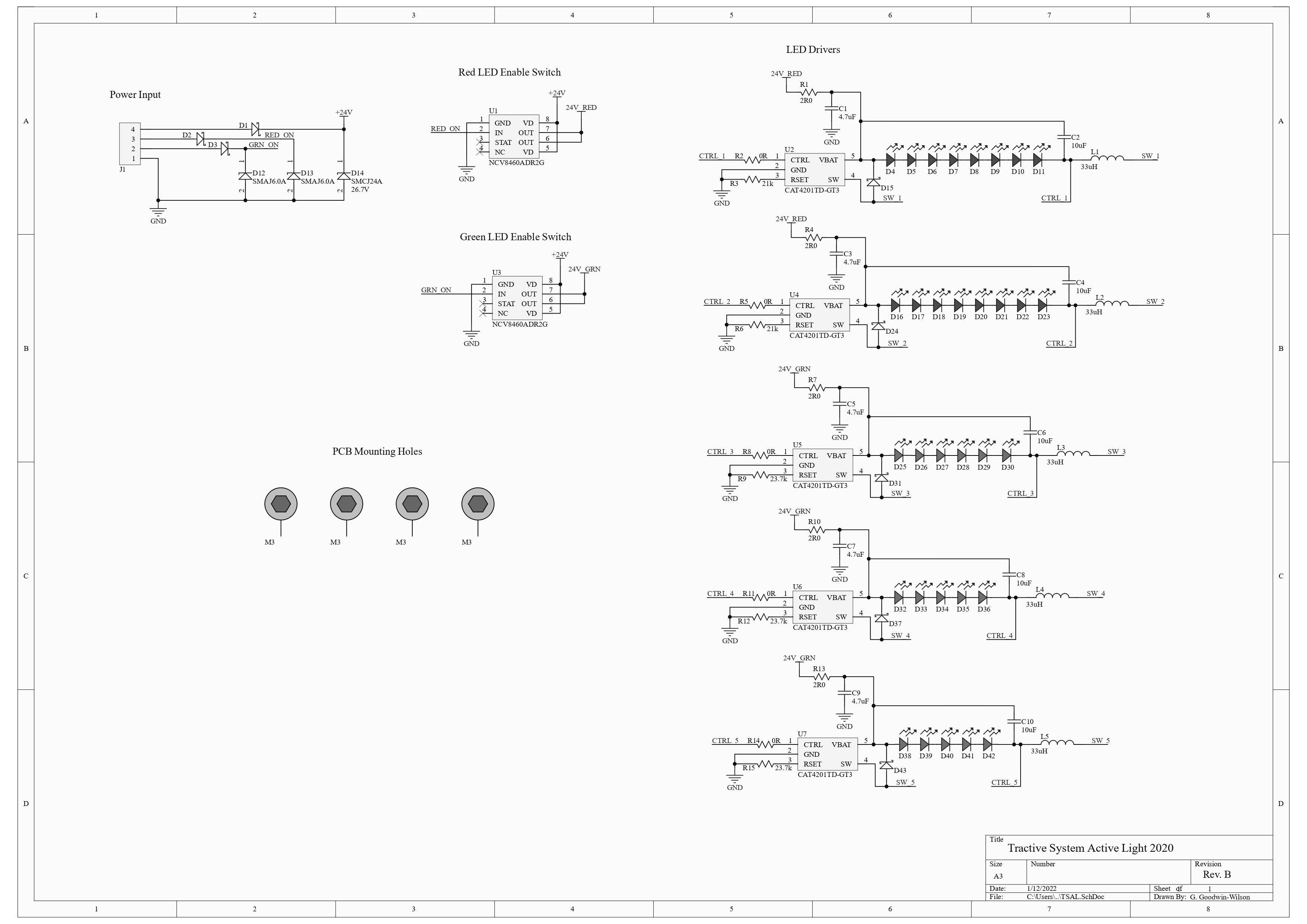
Schematic
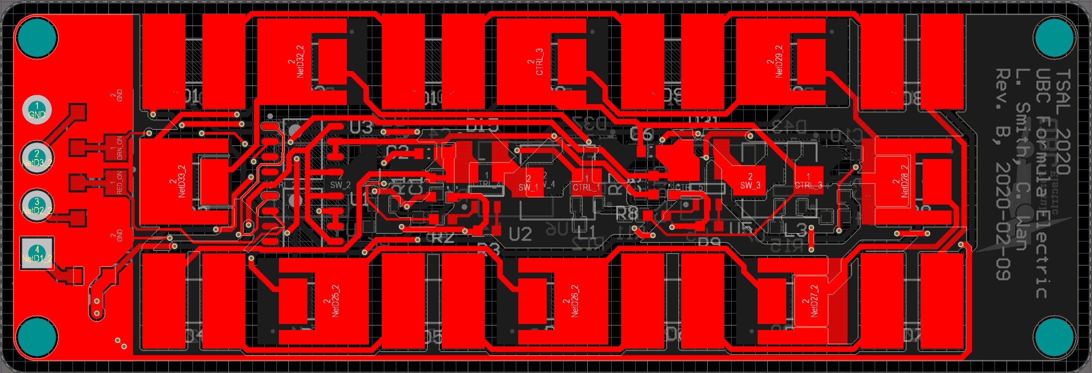
PCB Layers
Top Layer
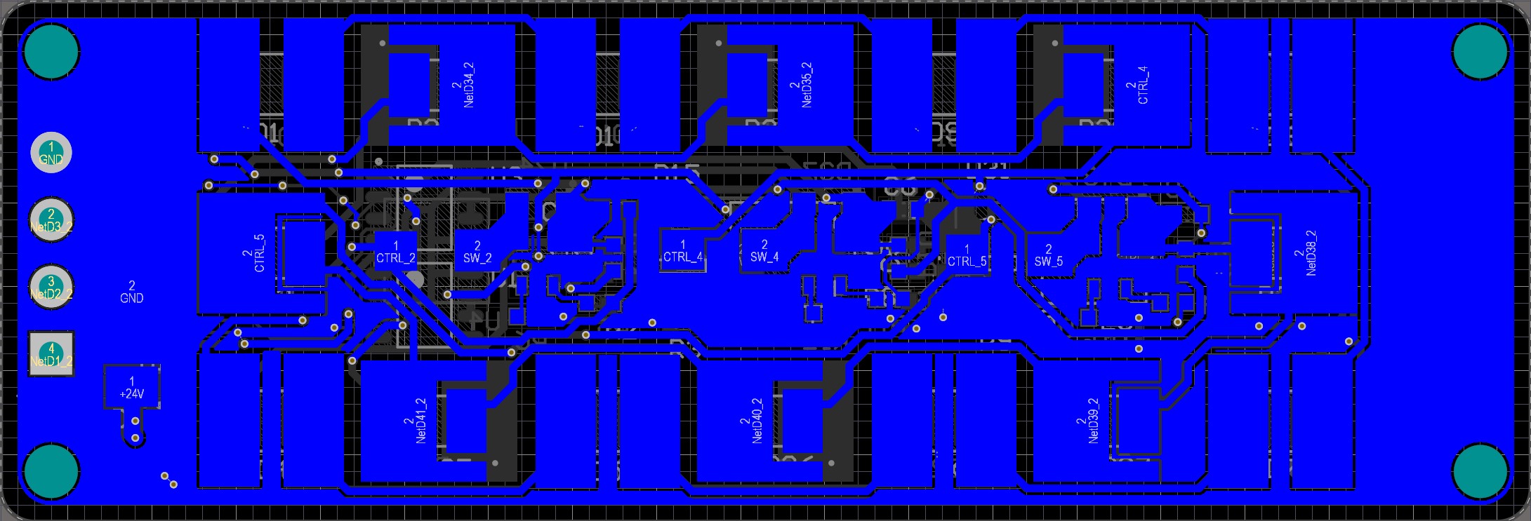
Botton Layer
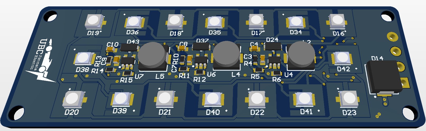
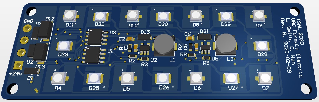
3d View
Top Layer
Botton Layer