Reflow Oven Controller
Introduction
Reflow soldering is a process in which a solder paste is used to temporarily attach tiny electrical components to the printed circuit board (PCB) after which it is subjected to controlled heat during which solder paste reflows in molten state, creating permanent solder joint.The machine in which this process takes place is called a reflow oven. In this project we converted an ordinary toaster oven to a reflow oven, by use of different hardwares and softwares.
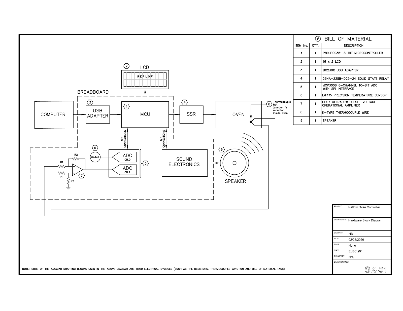
There are mainly six hardware blocks: Main FSM(Controls whole process),Thermocouple(Gets oven temperature), SSR(controls power supply to oven),Speaker(reads current temperature), LCD(to display temperature,FSM state, set soak temperature, and other UI), and ADC(Converts voltage to temperature). How these hardware communicates with each other is shown in figure 1, software codes to make each of the above hardware work is provided in appendix .
Investigation
Idea Generation
The task of this project was to control the working and operations of an electronic oven and alarm the user simultaneously regarding the happenings of the process. The project idea proposes a reflow oven controller with a sound output to satisfy the need to report to the user while using the device. The reflow oven controller will allow the user to turn the oven off when the maximum temperature level has been attained in order to avoid hazards.
Investigation Design
The design team consulted datasheets for electrical components to compare different options and choose the one best suited to the project. The information gathered from reading datasheets was used to build the hardware and also to write the software. Experimentation was conducted with the speaker by changing the CCU rate and observing how the speed of the sound changed.
Data Collection
Data regarding each electronic component being used was collected. Each datasheet was consulted and searched for relevant information. Also, sample code provided by Dr Jesus Calvino-Fraga was studied carefully. The team split into sub-teams, wherein each sub-team was responsible for the data regarding each of their systems - sound, display, hardware (main circuit).
Data Synthesis
The team synthesized the data collected from datasheets for different components: circuit components were connected according to pinout diagrams and compatibility of components in each sub-system was verified by consulting datasheets. If, for example two components were found incompatible, a step had to be taken back in the design process. The relevant and compatible information was then applied. The User Interface (LCD), the sound system, and the hardware, were all constructed after using the above method of data synthesis.
Analysis of Results
We analyzed the User Interface by testing the software and observing the LCD display. We tested the sound system using files with different sounds and speeds. We tested the main circuit by initially checking each connection using a multimeter and then finally using the oscilloscope to check for the correct wave output to guarantee the circuit’s competency. Intensive debugging was required when the desired output was not obtained.
Design
Use of Process:
The reflow oven controller is used to set adequate temperature and time for the four reflow stages [1]. Reflow soldering is one of the soldering methods which is more amenable to small-scaled manufacture [2]. More specifically, this method of soldering is mostly used for surface mount components in which small components are mounted directly onto the surface of a printed circuit board (PCB) [3]. Therefore, solder paste should go through four main stages controlled by the reflow oven controller to achieve the best result. To design the reflow oven controller, the team started the design process by dividing the project into separate main parts such as LCD, sound, and temperature electronics; each sub-team focused on a specific area. Eventually, we combined the contributions of each sub-team to get the final result.
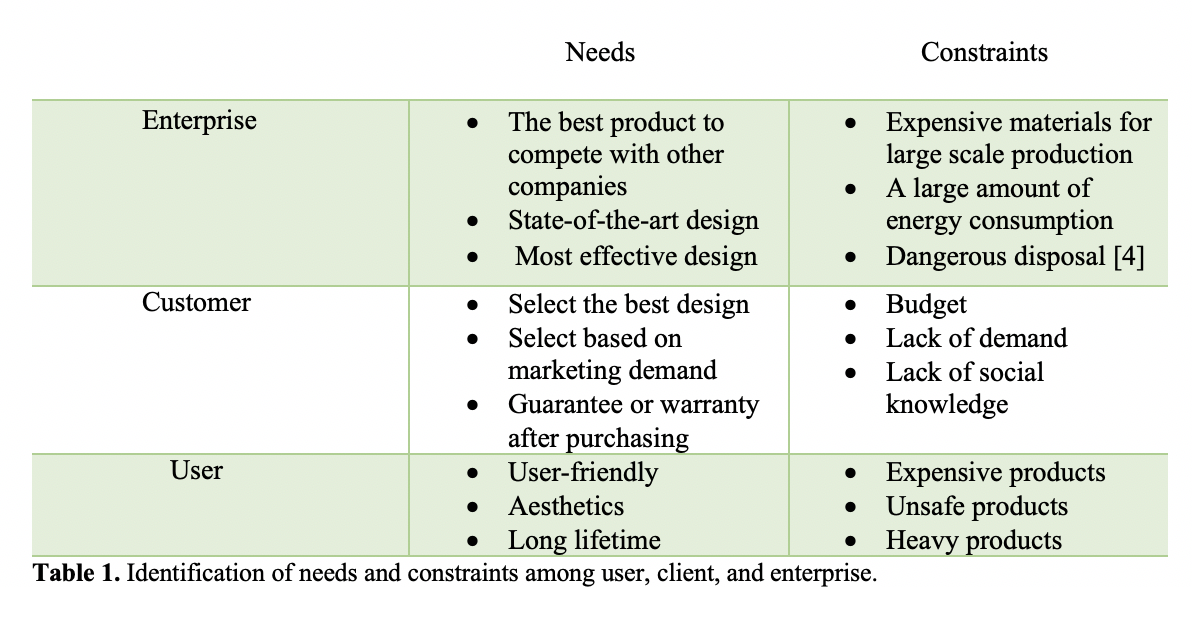
Need and Constraint Identification:
Problem Specification:
The team specified extra design requirements according to the needs and constraints mentioned above. As the budget is a significant factor, high quality and inexpensive components were used. Furthermore, the team considered adding features based on marketing demand such as a high-quality speaker and LCD. End-user needs and constraints were addressed by attempting to add an Arduino-programmed remote control as a more convenient method of entering data inputs when compared to the pushbuttons. Moreover, we considered non-English speakers by attempting to add an extra language (Farsi) to the sound system. Unfortunately, these last two additions were not completed by the project deadline.
Solution Generation:
The team was looking for alternative techniques to make small push buttons easier to use. Two main potential design solutions were Arduino remote control and using bigger pushbuttons. The user would be able to start, clear and stop the timer of the reflow oven controller by pressing remote control switches. The remote control is controlled by an Arduino board coded in C. Moreover, using bigger push buttons would have made the design more functional. Furthermore, it is inconvenient to check input data from a small LCD because there is a considerable amount of information that user needs to enter such as, soak temperature, time temperature, reflow temperature, and time reflow. The team was searching for potential solutions to make the User Interface more user-friendly by using a bigger LCD or having separate modes for each stage. Changing modes is possible by having a finite state machine which controls modes in each state. Finally, it was planned to make audio files in a language additional to English to be considerate to non-English users.
Solution Evaluation:
There were two potential designs to make push buttons more user-friendly. The team decided to choose Arduino remote control rather than using bigger push buttons because this technology is more unique in the market and more convenient. On the other hand, Arduino is cheaper to purchase than big push buttons as well as being more comfortable to use. There were also two possible designs to have a better display vision. It was decided to choose to change modes rather than buying a bigger LCD to keep the cost down for the final cost which was the main constraint of the project.
Safety/Professionalism:
Workplace safety was always a priority throughout the project. All of the team members used safety goggles while soldering. Professionalism was displayed throughout the entire process by supporting other team members and having respectful and effective discussions over the opinions between several potential designs. Even though the circuit blew up a few hours before the deadline, calmness was maintained and the team focused on getting the individual components to operate.
Detailed Design:
Hardware
Brief Summary of the Purpose of Each Hardware Block: The hardware was designed in order to meet the specifications of the reflow oven controller. Temperature electronics were designed to measure the cold and hot junctions so that the oven temperature could be determined. The sound electronics were designed to speak numbers from zero to 240 so that the oven controller could read the oven temperature aloud. An LCD screen and pushbuttons are used as a user interface. The LCD is used to display various parameters and the pushbuttons are used to modify key parameters (e.g. soak temperature) and to turn the oven on and off.
Decision Making and Background Knowledge: The P89LPC9351 8-bit 8051 compatible microcontroller was recommended for this project by Dr. Calvino-Fraga. The hardware schematic for the sound electronics was provided to the design team by Dr. Calvino-Fraga. The other blocks of hardware as shown in the hardware diagram were designed by the design team. The design team used knowledge acquired from previous ELEC 291 labs as a starting point for the design of the hardware. Specifically, the functioning of the LCD was learned in lab one. The knowledge required to design the temperature electronics was drawn from lab three. The temperature components used in this project were identical to those used in lab three with the addition of thermocouple wire and an op amp circuit to modify its output. There were two possible ADCs to choose from: 1) the internal 8-bit ADC of the P89LPC9351 microcontroller or 2) an external 10-bit MCP3008. The MCP3008 was chosen in this case since it had been used in a previous lab and therefore the team was more familiar with it. However, the disadvantage of choosing an external ADC was the loss of a few microcontroller pins that could have otherwise been used for another purpose.
Detailed Description and Evaluation of Hardware Blocks: This section describes and refers to the hardware blocks shown in the hardware diagram, SK-01.
Temperature electronics: In order to create a reflow soldering profile, a system of temperature electronics was designed to measure the oven temperature every second and send it to the microcontroller. Then the microcontroller uses the temperature measurements to signal transitions in the main state machine which is responsible for creating the various reflow soldering states. K-type thermocouple wire was used to measure the hot-junction temperature (inside the oven) while an LM335 was used to measure the cold-junction temperature (room temperature). Since the thermocouple wire produces a voltage of 41microvolts per degree Celsius difference in temperature, a difference amplifier was used to amplify the output voltage of the thermocouple wire. In order to achieve a gain of about 330, the resistor values of the op amp chosen were R1 = 3k and R2 = 1M. This amplified output voltage of the thermocouple wire, which represents the hot junction, is input to channel one of the MCP3008 ADC which is fed into the microcontroller. Similarly, for the cold junction voltage, the output of the LM335 is input to channel zero of the ADC and fed into the microcontroller. The actual oven temperature is the cold junction and hot junction temperatures added together.
Computer and USB adapter: A laptop provides power to the circuit through the BO230X USB adapter. These components are required in order to download encoded sound into the flash memory of the sound electronics block. Also, they are needed to download the microcontroller with software.
SSR: The SSR provides power to the oven. The power provided to the oven varies throughout the reflow process depending on the stage in the process. This variation is achieved through software by using pulse width modulation.
LCD and Pushbuttons: An LCD was connected to the microcontroller so that various parameters such as temperature and current reflow state can be displayed for the user to see. The LCD combined with various pushbuttons is the user interface so that the user can modify reflow soldering parameters and observe the current temperature of the oven and current state of the reflow process throughout the reflow soldering process.
Sound electronics and speaker: In order to be able to make the oven speak the current temperature and state of reflow process, hardware is set up. An external SPI flash memory, 25Q32, is connected to the SPI pins of the microcontroller to store the encoded sound. The internal DAC of the microcontroller (along with an interrupt service routine) is used to convert the encoded sound into audio. The LM386, an audio power amplifier, is connected between the DAC output of the microcontroller and the speaker so that the audio can be heard. A potentiometer was added so that volume could be adjusted.
Software
Brief Summary of the Purpose of Each Software Block: The software was built to meet the reflow oven control specifications. The three FSMs (temperature, sound, LCD) work together in a forever loop in order to output the power (pulse width modulation) to the SSR, the sound and the LCD display. Furthermore, the temperature of the oven and a stopwatch was designed to be constantly displayed on the homepage of the LCD. Also, inside the forever loop, one nonblocking pushbutton was dedicated to abort the reflow process, another one was used to stop the process and inside the LCD FSM, four push buttons were used to program the reflow and soak time and temperature.
Decision Making and Background Knowledge: A set of example codes were given by Dr. Calvino-Fraga which included test codes for the LPC9351, examples of ISRs (interrupt service routine) for both timers 1 and 2 with the LPC9351, examples of how to work with the LCD and the internal ASC0 of the LPC9351, and an example of FSM similar to the one needed for sound. Thus, using those examples and the knowledge from previous labs, the design team developed software that met the specifications of the oven controller.
Detailed Description and Evaluation of Software Blocks: This section describes and refers to the software blocks shown in the software diagram, SK-02.
Main Function: The function main in the oven_controller file is the main function of the software. Before the forever loop, it initializes all the variables and flags to their respective default values. Moreover, both the timers 0 and 1 are initialized to interrupt every 10 ms in order to have two timers running at the same time. The serial port and the SPI were also initialized at this location. Inside the forever loop, the PWM, LCD and Sound FSM were called and the pushbuttons to stop the oven or to abort the process were continually checked.
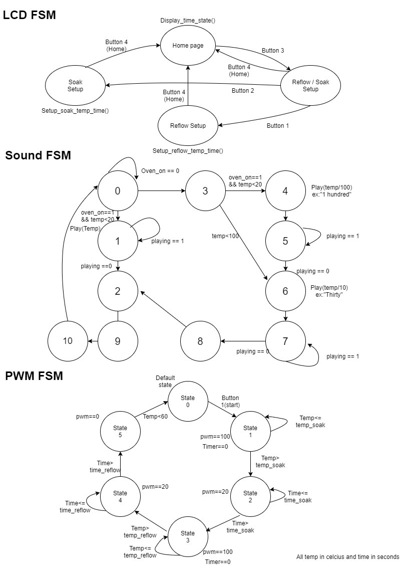
PWM FSM(line 1299, oven_controller.asm):
This FSM is the one that controls the oven and it is one of the most crucial pieces of code. The FSM’s objective is to change the percentage of power over the different stages of the reflow soldering process; it generates a square wave with a varying duty cycle. PWM is a register created to control the width of the pulses and thus, controls the power to the oven. This register was implemented in the timer 1 ISR, since the variable count10ms resets every second or in other words, every time it reaches 100 making the pwm percentage calculation very easy. In a few lines the function SUBB was used to turn the pin P0.1 high for 10ms times the pwm register value creating a squarewave. This implementation can be seen on line 300 until 310 of oven_controller.asm. (See Appendix)
The FSM starts as default on state 0. In this state, the pwm is equal to 0, that is the oven is off. After button 1 is pressed, it goes to state 1 where pwm is 100% and the timer is reset. When the board temperature exceeds the temp_soak variable, it jumps to state 2 where the pwm is 20%. It stays in the same state until the time exceeds the variable time_soak, then jumping to state 3 where the pwm is 100% and the timer is again reset. After the board temperature exceeds temp_reflow, it jumps to state 4 where the pwm is 20%. And finally when the timer exceeds time_reflow, the current state jumps to state 5 where the pwm is 0% . It then transitions to state 0 again for another iteration, if needed.
LCD_FSM(line 1232, oven_controller.asm) (See Appendix):
This fsm is responsible for the UI and to set the variables of the oven controller (time and temperature of soak and reflow). The UI consists of 4 different pages and 4 different buttons. As default, the LCD will start on the homepage where the temperature, the time, the state (reflow or soak) are displayed. Also the word “set” was displayed at the location of the button that changes to the setup page. On this page only the words “reflow” and “soak” are displayed at each corresponding button location. If button 2 is pressed, the page changes to the setup of soak state and if button 1 is pressed the page changes to setup the reflow state. On both pages the settable temperature and the time for soak and reflow (variables called :temp_reflow, time_reflow, temp_soak, time_soak) are displayed.They can be incremented with button 1 and decremented with button 2, and with button 3 it's possible to swap the variable that will be set. Moreover, button 4 is dedicated to the home button and it goes back to the home page. The UI is shown in Figure 2.
Sound_FSM(line 789, oven_controller.asm):
To make the speaker work, we first recorded numbers from one to twenty and then multiple of tens until 100, 200 and degree Celsius, using Audacity and then generated the index file by software computer sender provided by Dr. Calvino-Fraga. We then used the talking stopwatch code provided by Dr. Calvino-Fraga as the base code which we modified so that it speaks the temperature read by the thermocouple every 5 seconds by going to a particular sound index. To do so we set an interrupt which invokes sound FSM in the main FSM. Sound FSM communicates with memory 25Q32 of capacity 32 MegaBytes to access the sound at particular indices which is then transmitted to amplifier LM386 and then finally to the speaker.
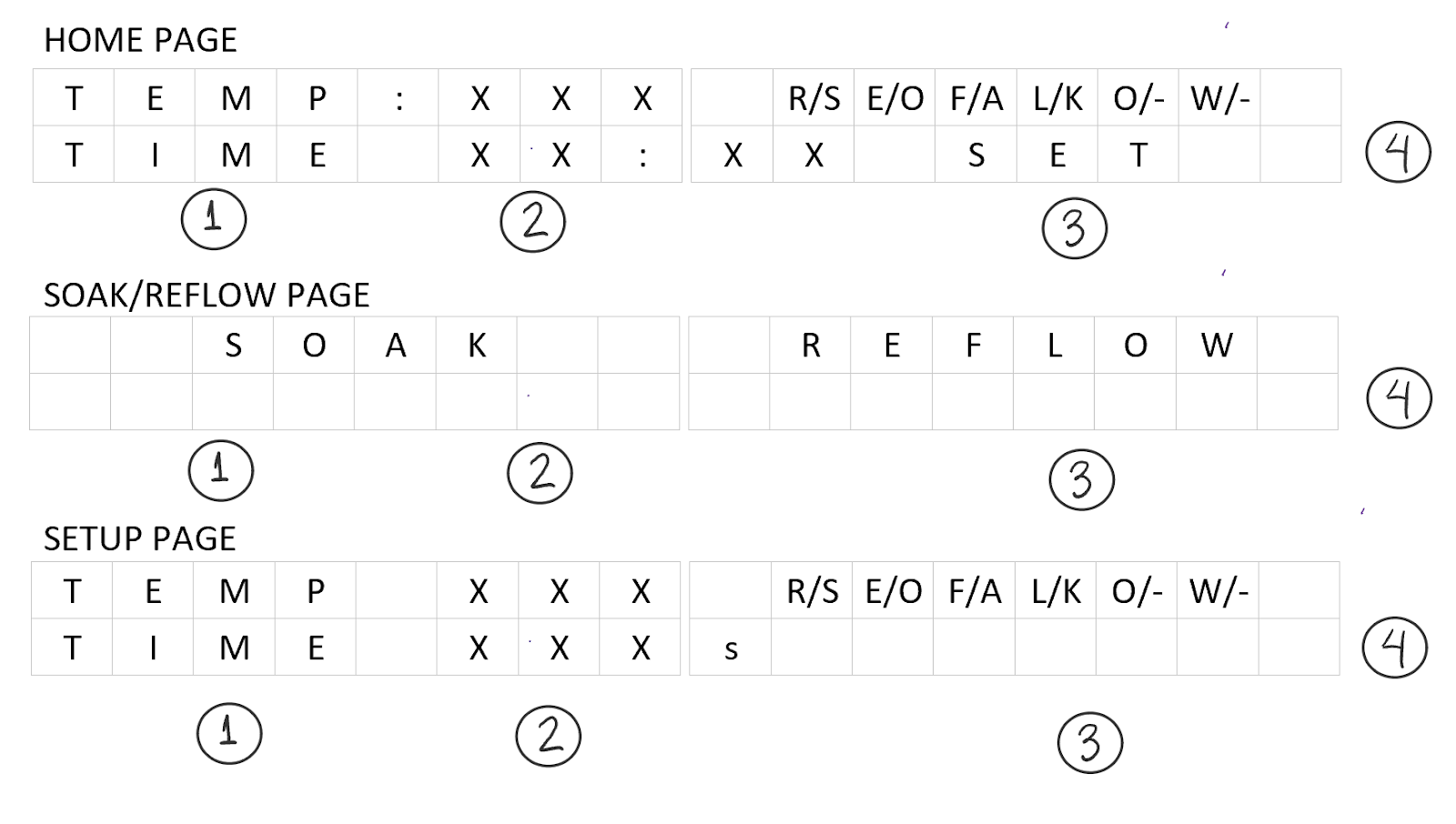
Figure 2: LCD UI, three possible configuration
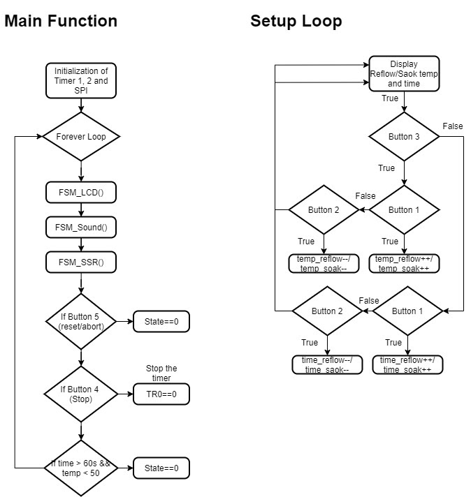
SK02: Main function and Setup loop to modify temp and time variables
SK-02: All three FSMs that are used on the main function
Solution Assessment
Evaluation of the Sound: First, the CCU ISR was tested by enabling timer 1 and calling the speaker’s finite state machine. This resulted in the speaker being triggered to speak approximately every five seconds as was specified in the requirements. Next, after completion of the entire circuit and code, the speaker’s working and competency were tested by making it speak various values of temperature.
Evaluation of the LCD: Initially, the LCD was programmed to display the timer on the home page. Then, reflow parameters and different modes of the oven were programmed. These additions were tested by adding pushbuttons. When the corresponding pushbutton was pressed, the modes would change accordingly from homepage to soak state to reflow state. Similarly, the end user could set the reflow parameters by pressing the corresponding pushbuttons. Finally, the timer was programmed to be able to start, stop, and reset using pushbuttons.
Evaluation of the Temperature circuit: Once the circuit for temperature measurement was built, as a first step in order to test measurements, software was written to print the cold and hot junction temperatures separately in putty. For example, if the thermocouple wire junction was at room temperature the hot junction value would show zero in putty and the cold junction value would be the temperature in the room; this makes sense since the temperature is the sum of the cold and hot values. Then, if the thermocouple junction was placed in the oven, the hot junction value would change to a larger value depending on the temperature in the oven but the cold junction value would remain room temperature. This method of displaying these two values in putty separately was helpful in the initial stages of testing to debug the software and get the temperature measurement system to work. Once it seemed to be working, the full temperature value was sent to putty and compared to the temperature value given by the following program that was provided by Dr. Calvino-Fraga: Multimeter_Temp.pyw. Temperature values from these two separate programs were compared for oven temperatures ranging from room temperature to 240 degrees Celsius.
A comparison of these two separate sets of 15 values are shown in the table below.
|
Putty Value (deg C) |
Multimeter Value (deg C) |
Absolute Error (deg C) |
|
83 |
84.5 |
1.5 |
|
84 |
84.4 |
0.4 |
|
88 |
89.8 |
1.8 |
|
91 |
91.6 |
0.6 |
|
94 |
94.5 |
0.5 |
|
95 |
97.0 |
2.0 |
|
103 |
103.7 |
0.7 |
|
105 |
104.8 |
0.2 |
|
107 |
107.3 |
0.3 |
|
119 |
118.2 |
0.8 |
|
120 |
120.5 |
0.5 |
|
124 |
124.5 |
0.5 |
|
125 |
126.2 |
1.2 |
|
141 |
141.1 |
0.1 |
|
142 |
142.9 |
0.9 |
Life-Long Learning
Project 1 had many things to offer us to learn, ranging from team management skills to practical skills. During this project we learned how to deal with different types of people in a team, how to manage time and get tasks done by the deadline which we think is a very important skill to attain. We learned more about Python as this project also involved the use of this programming language which we had never used or learned before . Knowledge from course CPEN 211 was very useful for this project. Specifically, the things we learned in CPEN about how FSMs and microcontrollers work as well as programming in Assembly. Besides CPEN 211, course ELEC 221 also helped us in understanding how ADC and DACs work (sampling rates). Labs from ELEC 201 also helped us a lot as we learned how to build professional circuits from that course. At the end of the project we experienced how to do reflow soldering.
Conclusion
The foundation of the project was a FSM that controlled the LCD Display, Temperature acquisition, speaker and PWM clock to the SSR relay. The FSM had multiple branching secondary FSMs that would execute the above mentioned functions sequentially.
The primary base structure of the the circuit board was the P89 family processor that was mounted on to a breadboard. Several sub circuit components executed essential functions as directed by the P89.
The sound files were stored in 253Q2 (flash memory). Upon activation of a new stage the microprocessor reads the sound file and converts it into an audio signal which is then sent to the speaker.
The temperature acquisition took place via a K-type thermocouple, the output of which was then fed into a single stage amplifier circuit. The voltage output was measured by an MCP3008 ADC in a master slave configuration.
The UI sub-circuit component was made by adding pushbuttons in a pull up configuration directly attached to specific pins of the P89 controller, this managed the adjustment of the various reflow parameters.
The PWM amp component amplified the output of the PWM signal by a factor of 10 such that all voltage values exist in the operating range of the SSR relay.
During the initial stages of our development, it was realized that the PWM output was in the range of milli V, while we needed at least 5000 milli V to power the SSR relay. The decision was to use a non-inverting op amp to solve this problem.
Also, the temperature values read by the ADC were linear, however the range was shifted by a constant. This problem was fixed by using linear regression in Excel and applying the end point corrections to the final value.
During the final prototype stages, the team accidentally supplied ~35V at 5A to pin 0 of the microcontroller chip killing it instantaneously . The chip was first replaced, however the certain sub circuit components would not interact with the new P89. It was fixed by changing the pin location.
The total time spent on this project among the six team members is estimated to be 300 hours.